How to Choose a RF PCB Supplier
RF PCBs work at high frequencies and require special handling. They are sensitive and can malfunction if not handled properly. You need to choose a manufacturer that understands this and is responsive to your needs.
Choosing a material with a similar loss tangent and tight substrate layers is crucial to ensure consistency. Also, pay attention to the CTE rate. This has a significant impact on drilling and assembly processes.
Material
A high-quality RF PCB has to be made with the right materials. These materials must be able to handle the high frequencies that these circuits operate at. They must also be able to handle temperature variations. The ability of the material to tolerate moisture is another factor to consider. This can be important depending on the environment in which the device will be operating.
The materials used to make a RF PCB are usually some combination of hydrocarbons, ceramics, and PTFE as well as different forms of glass. These laminates are then bonded together using copper, and the resulting board is then finished. The bonding materials are often chosen to balance cost with other properties such as dielectric constant, loss tangent, and coefficient of thermal expansion (CTE).
CTE is important because it affects the way in which rf pcb supplier the RF PCB performs. It determines how easily the board can withstand thermal stress, particularly during the soldering process. Having a low CTE means the board will be able to withstand thermal expansion and contraction without breaking.
RF PCBs are used in a wide variety of applications, from consumer electronics to missile defense systems. These devices must be able to operate seamlessly in an environment that can change rapidly, so they need a printed circuit board supplier with the right skills and resources to ensure that they can function at all times.
Layout
When designing an RF PCB, you should take several factors into consideration. These include the circuit’s function, working frequency, current and voltage, and key RF device kinds. The PCB should also have a well-balanced stack-up and uniform copper thickness. It should also be able to withstand high temperatures. Rogers FRPCBs are the best option for this purpose because they have higher thermal expansion coefficient (CTE).
In order to avoid coupling phenomena, traces carrying high-speed signals should be routed on a different layer than RF signals. In addition, dedicated layers should be used for routing power supply lines. These layers should have sufficient decoupling capacitors to reduce parasitic inductances caused by current-back-to-ground paths. It is also recommended that via holes be added on RF traces, which will help reduce the coupling between RF and other signals.
The length of the RF signal wire should be minimized to prevent interference with other signals and components. Moreover, it should be routed far away from high-speed digital traces and power planes. Lastly, it should be surrounded by smaller components to ensure that the impedance of the RF path is consistent with the required value.
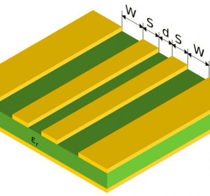
To achieve this, you RF PCB Supplier must use microstrip or stripline transmission lines with a width that is equal to the characteristic impedance of the circuit. This can be determined using one of many online tools.
Assembly
A RF PCB is a printed circuit board that operates at high frequencies. This type of PCB is essential for many electronic devices in our daily life, including smartphones and wireless electronic devices. It’s also an integral part of aerospace and military electronics. RF PCBs are more complex to fabricate than standard PCBs, and their operating efficiency depends on careful design.
A good RF PCB will have multilayers, which is crucial to improving performance and reducing costs. It also features a uniform stack-up that allows for the placement of fine pitch components. This is essential for high-speed signals, which need to travel quickly with little or no impedance. Moreover, the layered structure of a RF PCB makes it easy to maintain proper power and ground connections.
Another important characteristic of an RF PCB is its ability to tolerate thermal stress. This is an advantage in the military, aerospace, and automobile industries, where PCBs need to withstand high temperatures. Additionally, a RF PCB has a high tolerance power for noise, crosstalk, and other problems.
RF PCBs are an indispensable tool in the modern world, and they’re increasingly becoming more common. This is due to the fact that many electronic devices use RF signals, and these require very high-speed transmission. RF circuit boards are also used in cellular communication and wireless Internet of Things (IoT) devices.
Testing
The materials used in RF PCBs need to be stable under extreme temperatures. This is why they are usually a combination of hydrocarbons, PTFE and ceramics, among others. They should also have low thermal coefficient of expansion. This is one of the most important factors for reliability. It determines how much the board’s size changes with temperature. Using a high-quality material with a low CTE will ensure that your RF PCB will last longer.
Another factor to consider is the thickness of your RF PCB. It should be consistent throughout the entire board, as any variations can lead to loss. In general, thinner boards are better than thicker ones. However, it is important to remember that thinner boards have lower impedance than thicker ones.
In addition to being able to withstand high-frequency signals, the RF PCB should be plated with gold to protect the connectors from corrosion. It should also have a solid ground plane to minimize signal return paths and interference. It is also important to use microstrip or stripline transmission lines to match the impedance of the traces to that of the components and connectors.
It is also important to inspect the RF PCB after it is fabricated. This will ensure that the connections are properly aligned and that the RF PCB will function as intended. Visual inspection can detect any errors or anomalies that can compromise the performance of the RF PCB.

